Understanding the Mechanical Press: A Comprehensive Guide
The mechanical press is a cornerstone of modern manufacturing, playing a pivotal role in industries ranging from automotive to appliance production. Its ability to deliver high-force, precision shaping and cutting of materials makes it an indispensable machine. To truly understand its operation, one must start with its heart: the mechanical press diagram. This schematic representation is not just a drawing; it is a map that reveals the intricate interplay of components working in unison to convert rotational energy into powerful linear force.
Deconstructing the Mechanical Press Diagram
A mechanical press diagram illustrates the core assembly of components that define the machine's operation. While designs can vary (e.g., crank press, knuckle press), the fundamental principles remain consistent. The diagram provides a visual breakdown of how power is generated, transmitted, and applied.
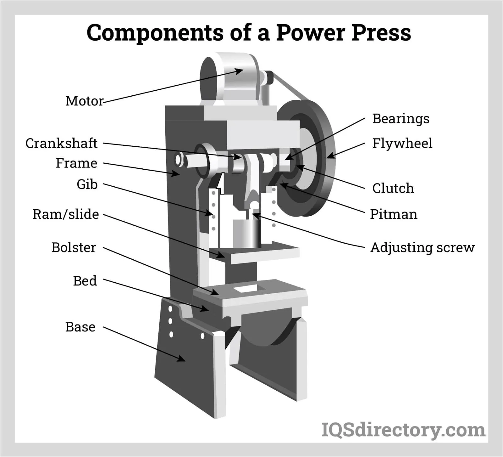 ="" class="caption" src="mechanical_press_diagram_annotated.jpg"/>Figure 1: An annotated diagram of a typical mechanical press showing major components like flywheel, clutch, crank shaft, connecting rod, and ram.
1. The Power Source: Motor and Flywheel
The journey of force begins with an electric motor. The motor constantly rotates a heavy flywheel, which acts as an energy storage device. Its significant mass and rotational inertia help maintain consistent speed and deliver the tremendous energy required for the pressing operation without overloading the motor at the moment of impact.
2. The Engagement Control: Clutch and Brake
Between the constantly spinning flywheel and the rest of the press mechanism lies the clutch. This is the "on/off" switch for the press stroke. When engaged, it connects the flywheel's energy to the drive mechanism. The brake is its critical counterpart, working to disengage the clutch and halt the motion of the press ram immediately when needed, ensuring safety and precision.
3. The Motion Conversion System: Crankshaft and Connecting Rod
This is the heart of the transformation process. The clutch transfers energy to a crankshaft, which converts the flywheel's continuous rotary motion into an oscillating, linear motion. Attached to the crankshaft is a connecting rod (or pitman arm). As the crankshaft rotates, the connecting rod moves up and down in a predictable, reciprocating path.
4. The Tooling Interface: Ram or Slide
The connecting rod is directly attached to the ram (also called the slide). This is the massive block that moves vertically within the press's frame. The upper half of the tooling, or the die, is mounted onto the base of the ram. It is this component that delivers the force directly to the workpiece.
5. The Foundation: Bed and Frame
The entire assembly is housed within a robust, rigid frame designed to absorb the immense forces generated without flexing. The bed is the stationary platform, bolted to the frame, where the lower half of the die is mounted. The workpiece is placed on the bed, and the ram descends towards it to perform the operation.
Operational Cycle of a Mechanical Press
The diagram brings to life a precise cycle of operation, which can be broken down into distinct phases based on the position of the crankshaft.
| Crank Angle (Degrees) | Phase | Ram Position & Action |
|---|---|---|
| 0° (Top Dead Center - TDC) | Cycle Start | Ram is at its highest point. |
| 0° - 90° | Downstroke | Ram accelerates downward. |
| 90° - 180° (Bottom Dead Center - BDC) | Working Stroke | Ram is at its lowest point, applying full force to the workpiece. |
| 180° - 270° | Upstroke | Ram begins to accelerate upward. |
| 270° - 360° | Upstroke Completion | Ram decelerates as it approaches TDC, preparing for the next cycle. |
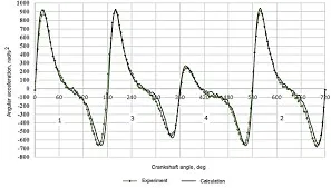 ="" class="caption" src="press_cycle_graph.png"/>Figure 2: A graph showing the position, velocity, and acceleration of the press ram throughout a full 360-degree crankshaft rotation.
Types of Mechanical Presses and Their Diagrams
While the crank press is the most common, the mechanical press family includes other types, each with a distinct diagram and force profile suited for specific tasks.
Eccentric Press
Similar to a crank press but uses an eccentric shaft or an eccentric hub on a standard shaft. This design allows for a adjustable stroke length in some models, providing greater flexibility for different operations.
Knuckle Joint Press
This design uses a hinged mechanism (the knuckle joint) to amplify force. Its diagram shows a vastly different linkage system that provides extremely high force at the bottom of the stroke over a very short distance, making it ideal for coining and embossing operations.
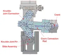 ="" class="caption" src="knuckle_press_diagram.jpg"/>Figure 3: Diagram highlighting the unique linkage system of a knuckle joint press compared to a standard crank press.
Conclusion: The Diagram as a Blueprint for Efficiency and Safety
The mechanical press diagram is far more than an technical illustration; it is an essential tool for understanding, troubleshooting, and optimizing press performance. For engineers, it informs die design and process planning. For maintenance technicians, it provides a roadmap for diagnosing issues with the clutch, brake, or drive train. For operators, understanding the basic concept fosters a greater awareness of the machine's cycle and inherent dangers. By mastering the language of the mechanical press diagram, one gains a deeper appreciation for the sophisticated engineering that drives modern mass production, enabling the creation of everything from car body panels to electronic components with relentless precision and power.
