Understanding the Working Principles of a Powder Compacting Press
Powder compacting presses, also known as powder compaction presses or powder pressing machines, are fundamental pieces of equipment in the manufacturing industry, particularly in powder metallurgy (PM) and ceramic forming. They are designed to transform loose, granular powder into a solid, shaped object—known as a "green compact"—through the application of high pressure. This process is crucial for creating components with complex geometries, high strength, and consistent density, which are used in everything from automotive engines to aerospace components and medical devices. Understanding how these machines work provides insight into a critical modern manufacturing technique.
The Core Objective: From Loose Powder to Solid Compact
The primary goal of a powder compacting press is to achieve three key outcomes simultaneously:
- Shape Formation: To form the powder into a specific, precise three-dimensional shape defined by a die.
- Densification: To increase the bulk density of the powder by reducing the voids (porosity) between particles.
- Green Strength: To create a "green" part that has sufficient mechanical strength to maintain its shape and be handled safely before the final sintering process.
This is accomplished not by melting the material, but by mechanically forcing the particles together through compaction, creating strong mechanical bonds between them.
Fundamental Components of a Powder Press
While designs vary significantly between mechanical, hydraulic, and servo-electric presses, as well as between single-acting and multi-acting models, all powder compacting presses share several core components:
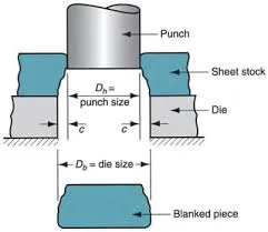
1. The Die
This is a hard, precision-machined container that defines the outer lateral dimensions (width and length) of the part being produced. It has a cavity where the powder is filled.
2. The Punches
Punches are rams that apply pressure to the powder from the top and/or bottom. A press typically has an upper punch and one or more lower punches. The punches form the top and bottom faces of the compact.
3. The Powder Feeder
This mechanism meters and delivers a precise volume or mass of powder from a supply hopper into the die cavity, ensuring consistency in the weight of each part.
4. The Press Frame
A robust, rigid structure that houses all other components and absorbs the immense forces generated during the compaction process, preventing deflection and ensuring accuracy.
5. The Drive System
This is the source of power, which can be a mechanical (eccentric or crank) system, a hydraulic system, or a modern servo-electric system. It controls the movement, speed, and force of the punches.
6. Ejection System
After compaction, the lower punch or a separate mechanism pushes the finished green compact up and out of the die cavity for collection.
The Step-by-Step Compaction Cycle
The operation of a powder compacting press is a cyclic process, often automated for high-volume production. The following steps describe a standard cycle for a simple single-acting press:
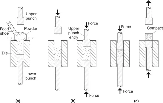
Step 1: Die Filling
The cycle begins with the lower punch positioned at the correct height to create a cavity of the precise volume required for the part. The powder feeder moves over the die, releasing a controlled amount of powder to fill the cavity. Any excess powder is typically scraped away, ensuring a consistent fill.
Step 2: Powder Compression
The upper punch descends into the die, entering the cavity and applying pressure to the powder. As pressure increases, the powder particles are forced together. They initially rearrange to fill voids, then deform plastically (for metal powders) or fracture (for ceramic powders), creating inter-particle cold welds and mechanical interlocking. This stage is where the majority of densification occurs.
Step 3: Pressure Dwell
At the point of maximum pressure, the press may hold the force for a brief moment. This "dwell time" allows for stress relaxation within the compacted powder, reducing elastic strain and minimizing the potential for cracking when the pressure is released. This step is more common in hydraulic presses.
Step 4: Punch Retraction (Decompression)
The upper punch retracts out of the die. The compacted part, now under significant elastic strain, expands slightly vertically. This phenomenon is known as "springback."
Step 5: Ejection
The lower punch is then raised, pushing the green compact up and out of the die. Careful control of the ejection force is critical, as excessive force can damage the relatively fragile part.
Step 6: Part Removal and Reset
The ejected part is removed by an automated arm or conveyor, and the lower punch returns to its fill position. The powder feeder advances again, and the cycle repeats.
Types of Compaction: Single-Action vs. Double-Action
The method of punch movement defines the density distribution within the part, which is a critical quality factor.
| Type | Mechanism | Density Distribution | Typical Applications |
|---|---|---|---|
| Single-Action Compaction | Only the upper punch moves; the lower punch and die are stationary. | Non-uniform. Highest density at the top (near the moving punch) and lowest at the bottom. Significant density gradient. | Simple, thin shapes where density variation is not critical. |
| Double-Action Compaction | Both the upper and lower punches move simultaneously towards each other, with the die remaining stationary. | More uniform. Pressure is applied from both ends, significantly reducing the density gradient along the vertical axis. | Standard for most technical components, providing more consistent mechanical properties. |
| Withdrawal (Die) Compaction | The press moves the die downwards while the upper punch applies pressure. The lower punch may also move to control ejection. | Highly uniform. This method is essential for complex, multi-level parts, ensuring consistent density in all sections. | Complex parts like gears, cams, and sprockets with multiple tiers. |
Key Process Parameters and Their Effects
The quality of the green compact is governed by several critical parameters:
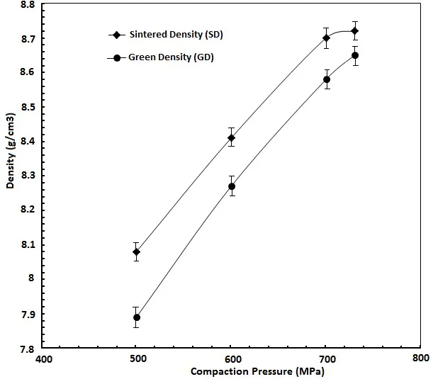
Compaction Pressure
This is the most crucial variable. Higher pressure generally leads to higher green density and strength. However, there is a practical limit; excessive pressure can cause tooling wear, lamination defects, or press overload. The relationship between pressure and density is often plotted on a compaction curve.
Powder Characteristics
The size, shape, and size distribution of the powder particles drastically affect flowability and compressibility. Spherical particles flow better but compact less easily than irregular, spongy particles. Lubricants are often mixed with the powder to reduce inter-particle friction and die wall friction, improving density distribution and easing ejection.
Pressing Speed
The rate at which pressure is applied can influence density. Too fast a speed can trap air, leading to defects. Hydraulic presses allow for precise control over pressing speed profiles.
Conclusion
The powder compacting press is a marvel of precision engineering, transforming a simple concept—applying pressure to powder—into a highly controlled and repeatable manufacturing process. From the synchronized movement of punches in a double-action press to the critical management of parameters like pressure and speed, every aspect of its operation is designed to produce a high-integrity green part ready for sintering. Understanding these working principles is key to appreciating how complex, high-performance metal and ceramic components are mass-produced with remarkable consistency and efficiency, forming the backbone of countless modern technologies.
